Knowledge centre
1. Drawings
To avoid any uncertainties and production errors, Kepser works in accordance with NEN standards. These can be requested from the Royal Netherlands Standardisation Institute (Nederlands Normalisatieinstituut – www.nen.nl). In this handbook, we make reference to the relevant NEN standards where applicable, but also provide additional information or clarification where the standards, in our opinion, require this.
A technical drawing must be totally clear to the person working on the shop floor. In the case of drawings, it is therefore essential to indicate the correct dimensions and tolerances clearly and precisely. When it comes to production control, programming CNC machines and maintaining an overview of everything (especially when using the same parts in different products), mono drawings are preferred.
Exchanging the CAD package
HiCAD can import and export the following formats: DXF, DWG, STEP, MTA, VDAIS, VDAFS, CATIA, VRML, FEM. To generate CAM codes for CNC-controlled machines, both 2D formats and 3D models can be used.
General information
- Ensure that contours are closed.
- Do not use double contour lines, as the laser will cut these twice.
- When programming laser-cut products, note the place of insertion, if necessary by indicating where the insertion absolutely must NOT be located. This is because the insertion usually causes an unevenness on the product, which can pose an obstacle to the product’s function or to subsequent processing. Fig. 1.1
- Drawings should preferably be provided at a scale of 1:1.
- Drawings should preferably be printed on A3 or A4.
- When producing the drawing, it must be known whether the product/sheet has a film coating. Bear in mind that film is cut from above.
- Bear in mind that bulb plate is cut with the • smooth side up.
- Indicate tapped holes with a 3/4 circle around • the drilled hole.
- Draw size-tolerated holes and contours in the • middle of the tolerance field.
- Use a functional size (in accordance with the • description in chapter 3).
- Draw sufficient views.
- Use mono drawings.
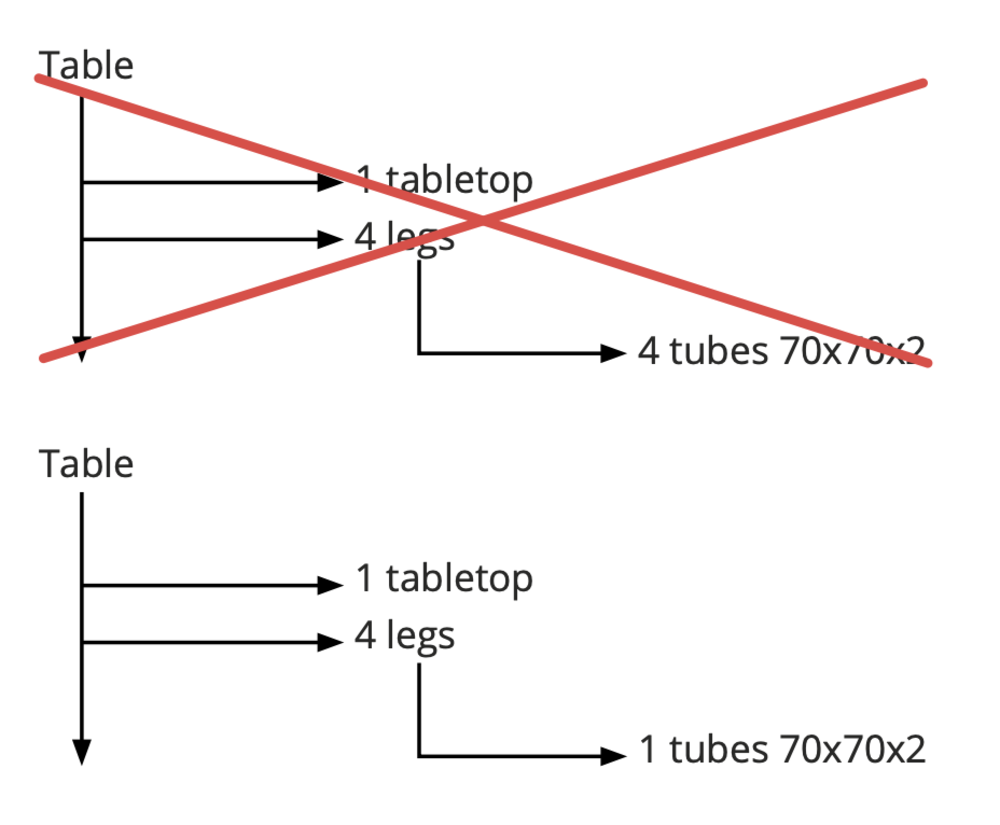
- Note quantities in the bill of materials on a one off basis. This makes it easier to see from the bill of material how many parts are needed and avoids the need to look for a lower level.
The drawing
Inscription as per NEN 5308
- Ensure that drawings (files) are identifiable They must be given a drawing number, version number, date and description of the product or project.
- Preferably also note the nature of the change and the revision date alongside the revision number.
- Specify the reference drawing if the drawing is derived from another product (length variant, mirror image).
- Choose a meaningful product name (do not, e.g., name everything ‘sheet’).
Dimensioning
Dimension technical drawings in accordance with ISO 129.
Inscribing dimension lines
Technical drawings, general principles for the indication of dimension lines, according to NEN-ISO 128.
Indicating dimensions
Technical product documentation text according to NEN-ISO 3098
- Write the dimensions where they will be looked for when making the workpiece, i.e. in the projection that most clearly depicts the shape or the profile of the workpiece.
- If further calculations have to be made during production to determine certain dimensions, errors could creep in. Therefore, take the fabrication of the product into account during the dimensioning phase. Choose absolute dimensions for drilling and welding. Fig. 1.3
- When setting chain sizes, opt for ‘from bending line to bending line’. Fig. 1.3
- Specify the total length of a workpiece.
- Keep internal and external dimensions separate. Place the length dimensions that refer to the internal dimensions above the figure and the length dimensions that refer to the external dimensions below the figure. Do not specify the setting radius if it is not important. Generally, Ri=S may be used.
- Take a function approach to dimensioning: use tolerances on operations that are achievable and do not tolerate smaller than necessary for the purpose in question.
Shape and position tolerances
Shape and position tolerances for technical drawings as per NENISO 1101.
Fits and dimensional tolerances
ISO system of fits, principles of tolerances, limit deviations and fits as per NEN-ISO 286. Preferred fits as per NEN 2807.
Be sure not to choose dimensional tolerances that are too tight, as this increases the production costs.
Roughness
Geometric product specification, indication of surface condition in technical product documentation as per NENENISO 1302.
Weld markings
Symbolic representation of welded and soldered joints on drawings as per NEN-ISO 2553.
Welding process as per NENENISO 4063. Quality level as per NENENISO 5817 and NENISO 10042. Welding position as per NENENISO 6947. Welding consumables as per NENENISO 544, ISO 2560 and ISO 3581.